|
Syllabus Sections:-
Types of Antennas
4D1 32
Recall the equation for calculating half-wavelengths and
be able to apply 'end factor correction' when calculating
the approximate physical lengths of simple dipoles and end
fed antennas.
Maths formula also most
certain to be used in this question !!!
As a
memory jogger let's show you some of the information you have
learned in previous courses.
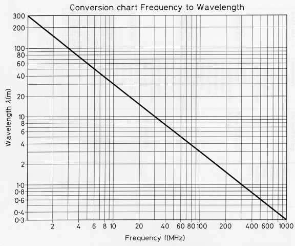
From the
Foundation Licence Course came the Frequency to wavelength
chart
From the
Intermediate Licence Course came the formula v = f  relating speed of
light v to frequency f and wavelength relating speed of
light v to frequency f and wavelength
v = f

The
velocity of light = the frequency x wavelength
and you
know that the over all length of a dipole is 1/2 long.
so 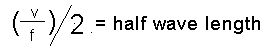
so the
EQUATION for calculating the overall length of a half wave
dipole is derived from the one above
( as it is
a 1/2 long
):-

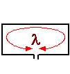
Example.
What is the length of a dipole for 3.6MHz ?
( 300/3.6
)/2 = 41.66m from end to end !!
'End factor correction'
But that is not the end of the story as this
Advanced syllabus introduces 'end factor correction'.
The
equation above would be correct for an aerial in free space,
however as we are operating from near to the ground the half
wavelength aerial will not be exactly equal to the half
wavelength depending upon several factors:-
These
items are all taken into account in what is called the "K"
Factor which the aerial length calculated above must be
multiplied by to give you a "better" approximation as to the
length of the aerial.
for wire
aerials of wavelengths up to 30MHz the K factor can be
taken as 0.95
From above
length of aerial is 41.66m
Apply the
K factor 41.66 x 0.95 = 39.57m Overall length.
This can
then be your starting point to prune the aerial to resonance
at the frequency of operation.
So in
addition to knowing the formula v = f x and rearranging to
the aerial calculation as shown above you must know the "K"
factor of 0.95 for wire aerials.
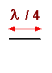
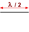
4D2 32
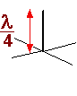
Recall the current and voltage distribution on the centre
fed dipole and  /4
ground plane antennas /4
ground plane antennas
When RF
energy is passes via the feeder line to a dipole antenna it
develop both voltage and current distribution as shown below.
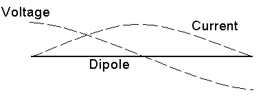
This
indicates that there is a high voltage point at the end of the
dipole but zero volts at the centre.
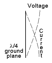 |
The ground plane
antenna is derived from the half the dipole and has
the same characteristic distribution of voltage and
current from one end of the dipole to the centre.
In the ground
plane the centre of the dipole is at the bottom so
voltage is zero and current at a maximum.
|
-----------------------------------------------------------------------------------------------------------------------------------------------------
4D2 32
continued Recall the
feedpoint impedances of half-wave dipoles, quarter-wave
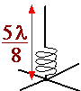
and loaded 5/8
vertical, folded dipoles, full-wave loops and end fed /4 and /2
antennas.
|
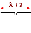
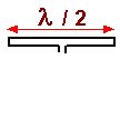
/2
dipole
|
/4
vertical
|
5/8
loaded
vertical
|
folded dipole
|
full-wave
loop
|
/4
end
fed
|
/2
end fed
|
 |
 |
 |
 |
 |
 |
 |
|
Feed Impedance of the various antennas
|
|
50 to 75 ohms
|
about 37 - 50 ohms
|
50 ohms
|
300 ohms
|
approx 100 ohms
|
Low Impedance |
High Impedance
|
-----------------------------------------------------------------------------
4D2
32 continued Recall
the effect of passive antenna elements on feed point
impedance and the use of folded dipoles in Yagi antennas.
In the
yagi only one element is driven the other elements are called
passive elements as they only have a passive effect on the
performance rather than the active of the driven element.
The
addition of the passive elements, directors and reflector, to
the driven element, which is usually a dipole, is to lower the
feed impedance. To bring the impedance back up to a level
where it can be fed with coax a folded dipole is used as the
driven element. If you look to the diagram above you can see
that the folded dipole has a higher feed impedance than the
dipole.
 Return loss Return loss 
|