|
|||||||||||||
|
|
|
||||||||||||
|
|
|||||||||||||
|
Syllabus Sections:- Propagation Radio propagation: key concepts 5A1 35 Recall that under free space conditions e-m waves travel in straight lines and spread out according to an inverse square law of power flux density and that the field strength, measured in volts/metre, drops linearly with distance. NOTE: Numerical calculations required at item 6E1 only. But make sure you are aware of the calculation as it can help to answer a question even if there is no calculation !!!  In free space the electric and magnetic waves travel in straight lines and spread out. This spreading out causes the signal strength to lessen according to an inverse square law of power flux density - which put simply means that the same amount of signal is covering a greater amount of space and thus the Rx'd strength will be less. Field strength drops linearly with distance but the Power Flux Density drop in line with the inverse square law so a distance doubled halves the Field Strength but reduces the Power Flux Density to a QUARTER of it initial value. If the field strength has halved, then the distance must have doubled so the Power flux density will be a quarter. As for Field strength it is related to 1/d (d = distance in meters) but for Power flux density it is related to 1/d squared. Imagine that you are standing inside a glass ball and you had to give it a coat of emulsion paint it you would used a certain amount of paint to fully cover the surface. The paint can equate to a certain amount of signal that you are radiating. If the ball now were say twice the size you would need more paint to give it the same coverage of paint as the smaller ball, BUT you do not have any more paint so you would have to add water to it and thin it down to make it cover the whole of the ball. The same happens with your radio signal, it too has to thin out or as we say "weakens" to cover the bigger area. You can see that there are more lines passing through the red rectangle nearer to the source than the one further away. ---------------------------------------------------------------------------------------------------------
Firstly the phrase "in phase" means that each wave started and finishes at exactly the same time as the other. Secondly
the phrase "at right angles" means each wave follows a path
exactly 90 degrees to the other and follows in the direction
of travel. Note
that the concept is drawn in Note that the E wave ( the Electrical wave ) is shown vertical and the H wave (the magnetic wave) is shown horizontal. However
the pattern can rotate but it will maintain the 90 degree
separation all the time. The
propagation, whilst it is in the direction of travel, the
waves themselves, actually develop at right angles to the
direction of travel, so you look carefully at the diagram. Also
a point to note is that the E wave is the one which determines
the polarity of the orientation of the antenna, either
vertical or horizontal from where the signal leaves to
propagate. ------------------------------------------------------------------------------------------------------------------------------------------------------ 5A4 35 continued Recall that in circular polarisation, the polarisation of the wave rotates as it propagates, either a right-handed (clockwise from behind) or left handed polarisation. These circular patterns of radiation are caused by the style of the antenna. The antenna instead of being a dipole or a vertical is an antenna that is a coil as shown in the animation below.
Let us say that the transmitter is connected to the left hand end. Then the signal makes it way along the antenna and then the diagram shows a break to indicate that the signal is radiated into the atmosphere. The signal is then is "collected" by a similar antenna which is coiled in the same direction - proved by looking at the diagram prior to the break appearing. The polarization is determined by the direction of rotation as viewed from behind. That rotation towards the right is called right hand polarization that towards the left is called left hand polarization. The concept that the antennas are wound in the same direction you will find is best to understand by winding a piece of wire around a pencil. Wind it on clockwise and then when you look at either end each winding will look in a clockwise direction. ------------------------------------------------------------------------------------------------------------------ 5A4 35 continued Recall that this is often used for satellite communications where the orientation of the satellite is indeterminate. This type of antenna is often used in satellite communication when the actual orientation of the satellites antenna will not be know but the satellite also has a helical antenna. ------------------------------------------------------------------------------------------------------------------------ 5A4 35 continued Recall that the transmit and receive antennas should have the same polarisation. So whilst the Tx and Rx antennas might both be helical they must both be wound in the same direction else large losses between the Tx and Rx signals will occur.
|
|||||||||||||
|
|
|||||||||||||
|
|
|||||||||||||


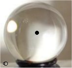

 fig. 12.1 page 78 .