|
||||||||||||||||||||||||||||||||||||||||||||||||||||||||||
|
|
|
|||||||||||||||||||||||||||||||||||||||||||||||||||||||||
|
|
||||||||||||||||||||||||||||||||||||||||||||||||||||||||||
|
From the previous page you should now have an understanding of : Resonance
Now to keep writing Capacitive Reactance and Inductive Reactance is rather long winded so we can adopt two symbols :- Capacitive
Reactance in an AC circuit is represented by Inductive
Reactance in an AC circuits represented by In the formulae that follow they use certain symbols :-
Inductive Reactance If we
draw a graph of inductive reactance
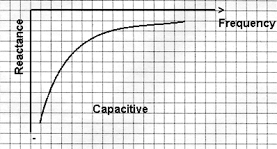
Capacitive Reactance If we
draw a similar graph for capacitive reactance
Syllabus Sections:- Tuned Circuits and resonance
At resonance XC = XL that
means that the capacitive and inductive impedance are equal
we can use the following equation Manipulating an equation can be quite daunting for some so this part will be further explained even more fully in the maths section.
So now that you have seen how the equation has been derived from first principles what could it be used for ? Well if you wanted to know what value of a inductor is required to bring a system to resonance whether that is an antenna or trap the formula would be used if you know the all but one of the factors in the equation so you would need in this example to know the Frequency and the Capacitor's value. Knowing how to use a scientific calculator would also help and manipulation of formula.!!! ----------------------------------------------------------------------------------------------------------------------- 2H2 15
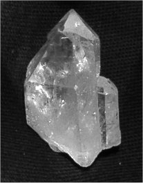
Recall the equivalent circuit of a crystal and that it
exhibits series and parallel resonance. A crystal resonator (or crystal for short) consists of a piece of "quartz" set between two conducting plates. If a voltage is applied to the plates the resultant electric field causes stresses in the crystal to occur such that it vibrates at a certain frequency that is in built due to the size and cut of the quartz. The equivalent circuit of a crystal with discrete components is a resistor inductor and capacitor in series and another capacitor in parallel as shown in the diagram with the point "A" and "B" each side of the parallel capacitor.
A piece of uncut Quartz crystal
2H2
15 Recall that crystals are manufactured
for either series or parallel operation and will only be
stable and correct on the marked frequency when used in the
intended manner. The crystal has two modes of resonance :- Accept a frequency - or low impedance as a series tuned circuit used to pass a frequency in a receiver Block at another frequency very close frequency or hi impedance or parallel tuned circuit used in an oscillator in a transmitter. When obtaining crystals the frequency is quoted for 32pf capacity parallel resonance. If that same crystal is used in the series resonance mode the frequency will be slightly different. -----------------------------------------------------------------------------------------------------------
3i.1 Understand that at resonance XC = XL and the formula for resonant frequency. The formula is :- You need
to be familiar with the equation We know that at resonance in a tuned circuit the reactance of the capacitor is equal to the reactance of the inductor and the two equation associated with reactance are:-
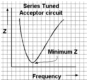
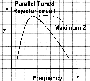
3i.2 Identify resonance curves for series and parallel tuned circuits |
||||||||||||||||||||||||||||||||||||||||||||||||||||||||||


 |
By varying the frequency of the input current, the
point where At the same time the overall resistance to the input current rises to a maximum and whilst the current through is at a minimum. At resonance this parallel tuned circuit is called a rejecter circuit. Take another look at the graph above. |
2H4 15 Recall
that voltages and circulating currents in tuned circuits
can be very high and understand the implications for
component rating.
Currents flowing in tuned circuits can be greater than the input current due to what is called the "magnification factor" which is also known as "Q" and discussed above.
Similarly voltage too can be higher than the input voltage.
THERE ARE MANY VALUES OF INDUCTANCE AND CAPACITANCE THAT FORM A "RESONANT" CIRCUIT AND HIGH CIRCULATING CURRENT, FOR A GIVEN FREQUENCY.
IT IS THE L/C RATIO WHICH
DETERMINES THE BANDWIDTH AND SELECTIVITY OF A TUNED CIRCUIT
AND ITS DYNAMIC RESISTANCE.
1.THE HIGHER THE L TO C RATIO THE HIGHER THE DYNAMIC RESISTANCE THE HIGHER THE Q, ( Rd OPPOSES THE CIRCULATING CURRENT),THE NARROWER THE BANDWIDTH, THE BIGGER THE VOLTAGE.
2.THE LOWER THE L TO C RATIO THE LOWER THE Q THE WIDER THE BANDWIDTH THE LOWER THE VOLTAGE. BOTH OF THE ABOVE HAVE CIRCULATING CURRENT BUT BECAUSE THE Q AND THE DYNAMIC RESISTANCE IS LOW THE VOLTAGE ACROSS THE TUNED CIRCUIT IN 2 IS ALSO LOW
Electronic components have what is called a "rating" and it is especially important that the rating is not exceeded else catastrophic failure of the component could occur and a domino effect occur which causes more damage than to the individually component.
CONSIDER THE TRAP DIPOLE ANTENNA AND A HIGH POWER BEING TRANSMITTED. FAILURE OF THE COMPONENT CAN OCCUR IN THIS EXAMPLE FOR TWO REASONS. 1. AT RESONANCE THE VOLTAGE RATING OF THE CAPACITOR CAN BE EXCEEDED. 2. OFF RESONANCE THE CURRENT CAPACITY OF THE COIL AND CAPACITOR CAN BE EXCEEDED ( CHECK THE REACTANCE)
-------------------------------------------------------------------------
2H4 15 Apply the formula for Q factor given circuit components values
The formula is :-= ![]() and
and ![]()
From the
above ![]() =
= ![]() and
we know that
and
we know that ![]() thus
thus
![]()
Also from above ![]() =
=  and we know that
 ![]() thus
thus
![]()
In all the formulae the following is true:-
![]() = frequency
in Hz
= frequency
in Hz ![]() = inductance
in henries
= inductance
in henries ![]() = capacitance
in Farads
= capacitance
in Farads ![]() = 3.142
= 3.142
so for a questions in the exam it is now just a matter of applying the formula to the variable given making sure that the correct multiplication factors are use as it is unlikely that you will be given the values of the variables as above but as milli henries and kHz or MHz and with the capacitors microfarads, so be prepared to do some manipulation.
2H4 15 Recall the definitions of the half power point and the shape factor of resonance curves.
The half
power point is where the level of the response has
fallen to ![]() (0.707
or 70.7%) of the maximum response or the -3dB level.
(0.707
or 70.7%) of the maximum response or the -3dB level.
The shape factor is the ratio of the bandwidth at -60dB and -6dB
Assuming that we loosely couple a signal generator into the inductor of a parallel LC circuit and measure the voltage across with an RF voltmeter
 |
Now let us sweep the input frequency and draw graph of the resulting voltage changes. |
|
|
|
![]() is
the resonant frequency giving a peak voltage,
is
the resonant frequency giving a peak voltage, ![]() .
.
The
points either side are generally accepted as limits of usable
frequency - This range ![]() to
to ![]() is the bandwidth [e.g.. 12kHz for speech] for
a parallel LC circuit, which could be the load in a power valve RF amplifier.
is the bandwidth [e.g.. 12kHz for speech] for
a parallel LC circuit, which could be the load in a power valve RF amplifier.
--------------------------------------------------------------------------------------------------------------------
2H4 15 Apply the equation for Q given the resonant frequency and the half power points on the resonance curve.
The circuit above shows a parallel tuned circuit with an RF voltmeter, such as is used in a common form of Q meter. Q meters give a measure of "Goodness" of a component or circuit. From the above resonance chart we have
The equation for the resonant frequency and half power points is :-
![]() =
= ![]()
which is also
the Bandwidth F1 & F2 compared to the resonant frequency FR = SELECTIVITY
Q of a response curve

If we had a response curve where the centre frequency FR was 10MHz and a band width of 200kHz (F1 - F2) what will be the "Q" of the circuit ?
![]() =
= ![]() =
= 
![]() =
= ![]()
2H5 15 Understand the meaning of dynamic resistance.
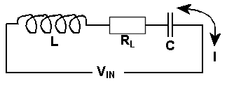
This expression dynamic resistance is used in parallel tuned circuits of inductor, resistor and capacitor. When such a circuit is at its resonant frequency the tuned circuit can be represented entirely by by resistance. This resistance is called dynamic impedance or dynamic resistance. This is an apparent resistance but exist with alternating current of the resonant frequency.
The
parallel resistance of a tuned circuit at resonance is ![]() x
x ![]() . This is known as the
DYNAMIC resistance
. This is known as the
DYNAMIC resistance
|
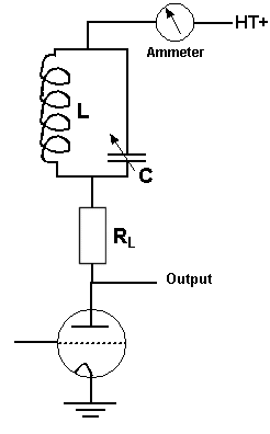
An example of this
is shown, a parallel tuned circuit in the "ANODE" of a
RF amplifier.
Let and To tune to
resonance we adjust The coupling
resistance to the next stage (Dynamic Resistance) is
The series RF resistance of the coil
=
|
2H5 15 Apply the formula for RD given component values
The formula is :- ![]()
Thus at
resonance in a parallel tuned circuit
of L C & R, the dynamic resistance
RD can be calculate from the formula ![]() where L (the inductance) is
in Henries, C (the capacitance) is in Farads and R (the
resistance) is in ohms.
where L (the inductance) is
in Henries, C (the capacitance) is in Farads and R (the
resistance) is in ohms.
The general expression for Dynamic Resistance is :-
![]() =
= ![]() which does not include any frequency component.
which does not include any frequency component.
It is obvious from this
that the larger ![]() compared
to
compared
to ![]() , the
higher will be the Dynamic Resistance and
, the
higher will be the Dynamic Resistance and ![]() .
.
So we can also express
the Q factor using RD in this equation ![]()
2H5 15 Understand the effect of damping resistors in a tuned circuit.
If we set a perfect tuned circuit into oscillation and then removed the source of the initial oscillation, it will carry on oscillating indefinitely. If then, we introduce some resistance into the circuit a little power is dissipated each cycle and the oscillation will die off exponentially. This loss of oscillation occurs whether the resistance is in parallel or in series with the tuned circuit. The resistance we have introduced is called DAMPING by damping resistor and reduces the Q-factor of a resonant circuit.
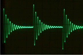
The picture above is of an actual oscilloscope trace where a tuned circuit is set in oscillation by a square wave which is superimposed on the trace just to show you where the square wave triggers the oscillation. Each sharp edge of the square wave causes the tuned circuit to oscillate and the damping effect of the imperfect tuned circuit is well shown. Note the shape of the curve of the reducing amplitude, the percentage of amplitude lost is the same for each per cycle hence the exponential curve.
NOTE: There is no such thing as a perfect tuned circuit so all circuits have some inherent damping which eventually stops their oscillation and such is the case with the tuned circuit pictured on the oscilloscope trace as it is the inherent damping of the inductor that caused the damping of the oscillations.
There are equations to calculate the equivalent series resistance caused by a parallel one but these are not required at this level.
Let's look at the real world situation an RF amplifier.
If we use a near perfect tuned circuit in an RF amplifier, once is excited it s oscillations would die out very slowly and any modulation at the amplifier input would be lost in the tuned circuit, so we "DAMP" it to the point where the oscillation dies out much faster than any modulation waveform. This damping, by the way, reduces the Q.
Another definition of Q is the ratio of Energy stored / energy lost (per cycle)
Q = Energy stored / energy lost (per cycle)
![]()
![]()