|
|
|||||||||||||
|
|
|
||||||||||||
|
|
|||||||||||||
|
Syllabus Sections:- Receiver architecture 3I1 25
Understand the block diagram of superheterodyne and double
superheterodyne receivers and the functions of each block.
So what is the meaning
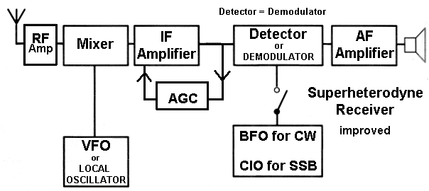
of the word the Superhetrodyne ?? Superheterodyne Receiver
-------------------------------------------------------------------------------------------------- The double Superheterodyne Receiver, also know as the communication receiver, as you would no doubt imagine is a far more complex piece of electronics than the "simple" Superheterodyne Receiver Take a moment to look through the diagram below and before reading through the explanation try to work for yourself what parts are doing what. In
the diagram above the RF Amplifier can also incorporate a
Pre-selector. A
pre-selector within the RF Amplifier is a band-pass filter
that blocks frequencies other than the wanted frequency
from passing through from the antenna into the radio
receiver's mixer stage. in other words it pre-selects the
wanted frequency !! The original signal in this case is 145.500MHz which mixes with the 1st Local Oscillator to give the Intermediate frequency of 10.7MHz and this frequency passes through all the other stages until the stages which extract the audio as AM, SSB, CW, FM and pass this recovered audio to the Noise limiter and onto the Audio Amplifier. The AGC can also extend to the RF amplifier and can be the source of voltage for a "S" meter. The double superheterodyne allows the choice of high frequency 1st IF, which is desirable to reduce problems with image frequency response, it can also can be know as Image Channel (an image frequency is another signal that is like a reflection in a mirror in that it is as far from the local oscillator as the wanted image). The low 2nd IF allows good filtering and plenty of gain to be easily realised. See also
the Fig 9.3 page 58 in the RSGB Full Manual for anther picture
to help you get a grasp of the design. The use of good filters fitted to IF1 and IF2 will be the key to good selectivity. As two local oscillators are used, there is scope for unwanted frequencies within the receiver. Note the use of the detector/demodulators to accommodate the three modes. The noise limiter seeks to reduce the volume of a loud "spike" of interference without affecting the volume of normal signals.
RF Amplifier
Intermediate Frequency Amplifier (IF)
AGC (Automatic Gain Control)
Detector (or Demodulator means the same is interchangeable)
Audio Amplifier (AF amp)
------------------------------------------------------------------------------------------- 3I2 26
Understand the function of a mixer, the generation
of the Intermediate Frequencies (IF) and other mixer
products The mixer combines the wanted amplified RF signal with the VFO signal (or as it is sometimes stated, with the local oscillator signal) to produce sum and difference frequencies of the RF signal and the LO signal which in fact are modulated identically to the incoming signal with the resultant frequency being the IF or Intermediate Frequency.
|
|||||||||||||
|
|
|||||||||||||
|
|
|||||||||||||
|
|
|||||||||||||


