

|
| |
Section 4
Feeders and Antenna
Feeders
4A1 Recall the correct cable types to use for RF signals and that coaxial cable is most widely used because of its screening properties.
In order for the 'RF' Signal to reach the Aerial from the Transceiver, we use what is known as a 'FEEDER'.
The goal is to carry the signal from the Transceiver to the aerial with as little loss as possible and with none or very little radiated signal.
![]() I am not sure what you mean can you explain
a little more. Ok.
I am not sure what you mean can you explain
a little more. Ok.
The Transceiver in its transmitter section creates a signal and presents it at its RF connector. This signal has to be transported to your aerial and it is transported by what is called a feeder. Any reduction (loss) in the amount of that signal delivered to the aerial due to it passing along the feeder must be kept as low as possible - else you could end up with nothing at the aerial! As there is usually only one RF connection to the Transceiver the feeder is used for both the transmitted signal and the received signal - where a transceiver has more than one RF connection it is usually for the ability to connect antennas covering different band but going into more detail is outside the scope required for the Foundation Licence Examination.
The feeder must also not radiate any of the signal (or as little as possible) else that radiated signal would not reach the aerial and could also cause problems by being radiated in the wrong place which will be explained more to you in the section on EMC.
So as I was saying :-
The feeder, comes in several forms, the most popular cable for this purpose, amongst Foundation Licence holders, is :- COAXIAL CABLE. It is easy to install and its construction is simple to understand.
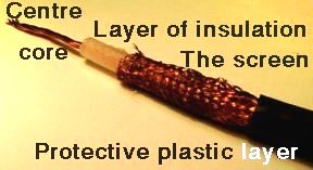
COAXIAL FEEDERS is an UNBALANCED FEEDER, and comes in a variety of diameters. It consist of a single or multi-stranded centre wire, which is covered by an insulating material of flexible plastic or polythene, with a braided wire sheath wrapped around it. This braided wire sheath is called the screen.
The outer braided wire (screen) is used to retain the signal within the cable. The screen must be continuous through the plugs and sockets, it is often soldered to ensure good connection.
 The following is of
interest only and not for the exam
The following is of
interest only and not for the exam
The Impedance of the coaxial cable is determined as the relationship of the distance between the inner wire, and the outer braided screen. The impedance of the coaxial cable is also determined by the diameter of the inner wire, and by the type of the dielectric insulator material between the inner wire conductor, and the outer screen braided wire conductor. Though coaxial cable comes in many different diameters, two common diameters of approx 3/16" and 5/16" are more often used in amateur radio, with the larger of the two being preferred due to its 'LOWER LOSS' characteristics for VHF use.
Identify
Twin Feeder & Coaxial as types of feeder.
Other feeders are RIBBON FEEDERS is a 'BALANCED FEEDER' consist of two insulated wires running parallel to each other and separated uniformly by spacers. Unlike a coaxial feeder this cannot be connected directly to a transceiver as it does not have a plug fitting suitable so it would be connected to and ATU. However as with the Coaxial feeder one wire will through the ATU be connected to the centre of the coax plug and the other to the ground side of the plug.
The "IMPEDANCE" of the ribbon feeder is determined by the diameter of the wire used, and the distance between the two wires in the ribbon feeder. This type of feeder is called 'BALANCED FEEDER', Normal 300 OHM ribbon feeder has a distance of approximately 10 mm between to the wires, which are separated with a flexible plastic type of insulator, in a 'Ladder' style pattern.
The Cables which are mainly used by Radio Amateurs are 'OPEN WIRE' Feeder, (450 OHM, 300 OHM and 75 OHM), and 'COAXIAL' Feeder (75 OHM and 50 OHM).
Understand
that twin feeder is balanced having equal and opposite signals in the
two wires.
The twin feeder as shown above is BALANCED as
it has equal and opposite signals in the two wire.
Understand that coaxial feeder is unbalanced with the signal on the centre conductor surrounded by a screen
The coaxial feeder is UNBALANCED with the
signal only on the centre conductor but this has and insulator
surrounding it and then a braid or screen surrounds the insulation
4A2
Recall that some RF energy is converted to heat in feeders so they
exhibit loss.
You need to know that some RF energy
travelling up the feeder is converted into heat and thus the feeder
exhibit a loss or reduction of energy (Watts) at the far end
of the feeder to that which is is entering the feeder.
Recall
that feeders cause loss of signal strength on both transmit and
receive; the longer the cable, the greater the loss.
You need to understand the a loss in feeder
going to an antenna when you are transmitting is similar to the loss
in the received signal coming from the antenna to the receiver.
Recall that feeder loss increases with frequency and that low loss feeders (lowest dB per unit length) should be used at VHF and UHF
Another thing
regarding feeders is the as FREQUENCY increases so the amount of LOSS of
signal increases. Losses in different types of coaxial feeders is due to
their design and thus when using higher frequencies you need to use the
lowest loss in the cables as measured in dB per unit length.
![]()
The origin of some of the text on this page is from the RSGB with additions by the web master