

|
| |
Technical Basics Part 3
Resistance
2C1 Q7 Understand that
resistance is the property of a material that opposes the flow of
electricity.
Lets
see what you learned earlier ....
You need to know what a resistor is to understand the next part. Imagine you
are pushing against a wall but the wall does not move but it does offer
what you would feel as a resistance to your pushing. So with that in
mind a resistor acts like the wall to a flow of electrons, a current
flow.
or you could think of it like this :- How many of you have played with a garden hose and put your finger over the end and been able to reduce the flow of water whilst say filling a bucket ? What you were in fact doing was providing a resistance or opposition to the flow of water in the hose and which resulted in a much reduced amount of water flow.
Which
ever way you want to think about it you now understand what resistance
is all about.
When
an electric current passes through a resistor its resistance results in
the conversion of the electrical energy, the flowing current, to heat
energy and this makes the resistor warm up and if there is too much
current flowing the resistor can be destroyed.
Recall that the unit of resistance is the Ohm
(Ω).
Resistance has the abbreviation R and the unit of measurement is the Ohm symbol Ω
As a reminder in electrical circuits a resistance provides an opposition to the flow of electrons and thus reduces the amount of current that can flows in a circuit.
Recall that the current (I) through a resistor
(R) is proportional to the voltage (V) across that resistor.
Let's start at the beginning. A voltage source ( a potential difference), V, drives an electric current in amps , I , through resistor with a resistance in ohms, R, and these three items obey what is know as Ohm's law: V = IR. The law was named after the physicist George Ohm, who published a treatise in 1826 of the relationship between Voltage, Current and Resistance. So the discovery which George Ohm proved by experiment that a precise relationship exists between current, voltage, and resistance still hold true today and is something you need to learn.
Use Ohm’s law to calculate the value of any one of the three quantities (voltage V, current, I and resistance R) given the other two.
V = I x
R Voltage = Current x
Resistance
When you are given two of the items the third can be found by manipulation of the formula but this is more easily shown in what is called a magic triangle.

The animation shows how knowing two elements you can work out the third element.
Just cover the one you do not know and then if that was volts it leaved current and resistance which being on the same bottom line are multiplied together. If you know current then covering that one leaves volts above a line and resistance below a line so volts are divided by resistance.
Likewise knowing resistance leaves volts above a line and current below a line so volts are divided by current.
...................................................................
Questions in the exam will not necessarily be calculation as the syllabus states Recall the relationship between Potential Difference (Voltage ), Current and Resistance. so the question may just be a matter of manipulation the equation to state for instance "The formula for voltage is ??" and you would need to know it is V=IR or any of the other combinations eg. I=V/R R=V/I
.....................................................................
Another way of using this part of the syllabus is to ask what happens if ?
For instance What happens if the Resistance in a circuit is doubled?
You would need to think clearly about this the voltage is not changing but the resistance is 2x the original value.
to find I (Current) we have V (Volts) divided by R (Resistance) in the first case and then V divided by 2x R
if necessary put in your own values say V = 10 and R = 5 then 2x R = 10
working out I = 10 / 5 = 2A
and I = 10 / 10 = 1A
so the solution to the problem set, What happens if the Resistance in a circuit is doubled?
Answer "It halves"
so even though you have not been given any variables you can introduce them yourself to reach the answer.
Understand that where a supply feeds more than
one component or device the total current is the sum of the currents in
the individual items when connected in parallel.
This
is a difficult concept to understand but what the syllabus is saying is
that is you had a single source of water (the current in an electrical
circuit) which then went into a Y piece which split the single
source of water into two pipes that the total amount of water
flowing through the two pipe would be exactly the same as the
amount flowing in the feed pipe.
2C2 Q7 Understand that the sum of the voltages across a number of resistors in series equals the supply voltage.
Before you can
understand the syllabus part you need to know that when measuring a
voltage in a circuit you do not break into the circuit as you would need
to if measure current but can touch the probes of your meter on the ends
of the components in this case resistors.
Now If you have a number of resistors connected in series, like a string of sausages, as resistors are resisting current flow the nearer you go towards the negative connector of the circuit the lower will be the value you see measured in volts on your meter and conversely the nearer you go to the positive connector the higher will be the reading in volts on your meter.
In fact if you note down all the readings
on the volt meter as you progress down the circuit at the ends of the
resistors and add them up it will equal the voltage reading that you
can take across the supply + positive and - negative connectors.
2C4 Q7 Recall that polarity must be correct for electronic circuits to function correctly, or damage may be caused.
You need to know that for many electronic circuits to function correctly that the polarity of a the potential difference source (Voltage) is importance is not relevant if a filament bulb is used but that electronic circuits can be damaged by the wrong polarity.
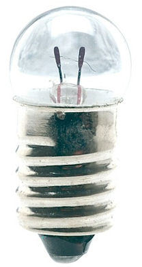 |
This is the filament light
bulb and it is hoped that you can see the very
thin wire passing from one electrode to the other.
The polarity of a battery when connected to the
bulb is not relevant. This is the special case
which you must understand. |
Polarity of a battery + and -
A battery has two terminals to which you could connect wires. One is marked + and one marked - . The + indicated the positive terminal and the - the negative terminal.
Polarity sensitive
There are very few electronic components that are NOT said to be "polarity sensitive".
 What does polarity sensitive mean ? This
means that if a positive terminal of a battery ( the one
marked with a + ) is connected to where the negative terminal
( the one marked with a - ) should be connected and the
negative connected to the positive terminal DISASTER will
occur in most circumstances and the components ruined or a
fire could occur !! So if you connected a battery the wrong
way round in a portable battery radio not only would it not
work when the battery is connected the wrong way round it will
almost certainly not work when then connected the right way
round.
What does polarity sensitive mean ? This
means that if a positive terminal of a battery ( the one
marked with a + ) is connected to where the negative terminal
( the one marked with a - ) should be connected and the
negative connected to the positive terminal DISASTER will
occur in most circumstances and the components ruined or a
fire could occur !! So if you connected a battery the wrong
way round in a portable battery radio not only would it not
work when the battery is connected the wrong way round it will
almost certainly not work when then connected the right way
round.
Let's remind you of what you read
earlier and hope that it is now clear in your mind !
HOWEVER --- A filament lamp such as a torch bulb - relies upon the battery pushing an electric current through the filament in the bulb to shine BUT the bulb do not mind which way round the terminals of the bulbs are connected to a battery. It is therefore safe to connect either terminal of the battery to either of the wire leads from the bulb.
A lamp (bulb) does not mind which way round the electrons are pushed by the battery.
Why does it not matter
which way round they are connected ? It is because the
filament bulb is just a special piece of wire inside a glass
holder and like any other piece or wire it can be connected
which ever way round happens first!
Electronic circuits
When connecting a battery to an electronic circuit whether it is a simple circuit on the bench or a complex one such as a battery radio the polarity of the battery connection of the piece of equipment must be carefully observed.
Failure to observe the polarity and to connect the battery with the wrong, or what is sometimes called "reverse" polarity the piece of equipment will :-
a. not work and
b. may have been damaged to such an extent that it might never work again even with the battery connected the right way round.
This use of correct polarity will be particularly important to you when connecting your first transceiver to a power supply. You will be shown how to connect up in the practicals but when doing it your self should you get it wrong because the currents that could flow from the power supply will far exceed those from a "dry cell" battery not only could damage to the equipment result but this could cause a fire.
OBSERVE CORRECT POLARITY when connecting electronic equipment.
![]()
The origin of some of the text on this page is from the RSGB with additions by the web master