

|
| |
Section 3
Transmitters and Receivers
Transmitter concepts
Reference below will be made to this diagram as it shows a Simple block schematic diagram or "concept" diagrams of a transmitter.
This diagram is from the tutor notes for the course and would be used for any assessment questions on this topic. The diagram is not intended to relate directly to any particular transmitter it is intended only to show the basic functions that are performed within a transmitter.
Each part of the transmitter is called a "stage" hence the Mic is connected to the Audio stage and so on.
1= Audio Stage. The very low signal from the microphone (mic) is amplified to the required level and the passed onto the next stage.
2= Modulator stage mixes the signal from the Audio stage with the Frequency generator to give the signal that the last stage amplifies.
3= Frequency generation Stage. This generates the frequency to be transmitted and is mixed in the modulator with the audio stage in readiness for the amplifier stage.
4= Power Amplifier stage. This amplifies the small signal from the modulator and send it via the feeder (usually coax but not always) to the antenna.
3A1
Recall that the function of a radio transmitter is to send information
from one
place to another using electromagnetic radiation/wireless technology.
Recall that the process of adding information to a radio frequency
carrier is known as modulation.
The radio transmitter performs the function of converting information which in most cases is audio information and then by the use of an antenna allows this resulting radio frequency (electro magnetic radiation) to move from one place to another using and this is also called wireless technology.
3A2
Recall that the audio (or data) signal is modulated on to the radio
frequency carrier in the modulation stage of the transmitter.
2=Modulator stage. This stage mixes together the signal from the Audio stage and the Frequency generator stage in preparation for amplification in the 4th Stage.
Recall that modulation is achieved by varying the amplitude or frequency of the carrier, resulting in AM or FM modulation modes.
The modulation stage determines whether the output RF signal will be AM or FM depending whether the Amplitude is changing hence Amplitude modulation (AM) or the Frequency is changing hence Frequency Modulation (FM).
Recall that information can be carried by AM, SSB or FM.
Depending upon whether the modulator varies the amplitude or the frequency of the carrier will the output be AM or FM
AM is the variation of the Amplitude where as FM is the variation of the Frequency.
Recall that data may be transmitted by modulating the carrier using suitable audio tones, commonly two or more, generated by an audio interface such as a computer sound card.
DATA can also be carried on AM, SSB or FM but requires that the data is passed through a radio modem ( modem = modulator / demodulator) to change the 0 or 1 of the data code into two different tones.
A particular type of data mode is called "Packet" and this requires a TNC or terminal node controller which converts the typed letters from a computer into data - 0s and 1s and then put them together into "packets" which are sent at high speed as bursts of data.
3A3 Recall that when radio frequencies are modulated (mixed) with an audio frequency the new frequencies that are generated are called sidebands.
When the radio frequency is mixed with the audio frequency it generates as we learned above and Amplitude signal and this comprises of two frequencies and these frequencies are called sidebands which are a refinement of the AM signal.
Recall that amplitude modulated signals contain two sidebands and the carrier.
Looking at this in more detail the Amplitude Modulated Signal contains
the two sidebands and a carrier.
Recall that a SSB modulated signal contains only one sideband.
When we look at SSB modulated signal (also know as Single Side Band) so called as it only has one side band and no carrier.
3A4
Identify diagrams representing audio, an RF carrier, amplitude modulated,
frequency modulated and CW radio signals.
Before we look at the composite drawings of both AM and FM let's look as something that is a little simpler.
Whilst the wave form shown is in fact a sine wave we are using is here as a simple representation of an audio signal. An Audio voice signal is in fact a very complex wave form which does not need to be covered in this course.
This audio signal is the same signal input notwithstanding whether the final output being AM of FM.
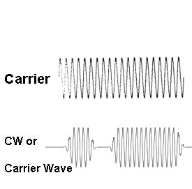
As with the Audio signal this is a representation of an RF carrier wave and is the same whether the output is AM of FM
Understand the terms carrier, audio waveform and modulated waveform.
Note: Table 2 shows appropriate diagrams.
Below are two sets of diagrams note the each have the Audio Wave and Carrier Waves (also just called Carrier) which are the same it is only when the carrier is mixed with the audio does the resultant wave form of the RF signal become either FM or AM.
 |
 |
 |
| Bottom image is an | FM modulated signal | AM modulated signal |
The images of the modulated signals (bottom diagrams) on the left hand side above represent FM and on the right hand side represent the AM.
The diagram below represents a CW radio signal of the letter "A". CW is just the on and off keying of the carrier wave without any audio or modulation.
![]()
The origin of some of the text on this page is from the RSGB with additions by the web master