

| |
Section 3
Transmitters and Receivers
Transmitter architecture
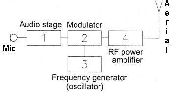
3B1 Identify the items in a simple transmitter block diagram and recall their order of interconnection: Microphone, audio (microphone) amplifier stage, frequency generation stage, modulator stage, RF power amplifier stage, feeder and antenna.
Below is shown a Simple block schematic diagram or "concept" diagrams of a transmitter.

This diagram is from the tutor notes for the course and would be used for any assessment questions on this topic. The diagram is not intended to relate directly to any particular transmitter it is intended only to show the basic functions that are performed within a transmitter.
Each part of the transmitter is called a "stage" hence the Mic (Microphone) is connected to the Audio (microphone) amplifier stage and so on.
1= Audio Stage. The very low signal from the microphone (mic) is amplified to the required level and the passed onto the next stage.
2= Modulator stage mixes the signal from the Audio stage with the Frequency generator to give the RF signal that the last RF power amplifier stage which makes the RF signal larger.
3= Frequency generation Stage. This generates the frequency to be transmitted and is mixed in the modulator with the audio stage in readiness for the amplifier stage.
The origin of some of the text on this page is from the RSGB with additions by the web master