

| |
Section 3
Transmitters and Receivers
RF power amplifiers

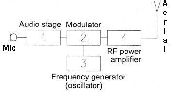
3F1 Recall that the RF power amplifier stage increases the power of the modulated RF signal to the final output level.
RF power amplifier stage. This is the final stage and it amplifies the modulated signal and is connected to the antenna connection on the rig. From here usually a coaxial connector links with a coaxial feeder delivers the signal to the antenna.
This is the stage that also controls how much amplification is given to the signal before it is sent to the antenna for radiation.
3F3 Recall that the RF power amplifier output must be connected to a correctly matched load to work properly and that use of the wrong antenna can result in damage to the transmitter.
In the section on antennas and feeder you will learn (or have learned) that an antenna has to be matched to the transmitter frequency. It is this power stage of the transmitter that could be damaged if not connected to a properly matched antenna. This is where the ATU comes in to properly match the antenna and feeder to the transmitter output impedance which is usually 50 ohms.
If you used the wrong antenna or no antenna at all then damage to the transmitter could be the result.
The origin of some of the text on this page is from the RSGB with additions by the web master