|
|
|
|
Bredhurst Receiving and Transmitting Society |
Part 2 |
|
|
|
|
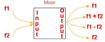
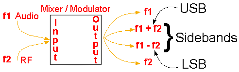
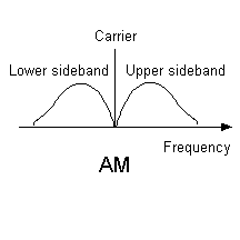
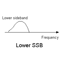
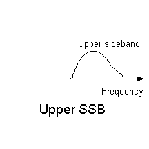
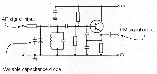
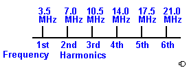
4c Mixers 4c.1 Recall that when two frequencies are mixed together, the mixing process generates new frequencies. Recall that these new frequencies are equal to the sum of and the difference between the original frequencies. This part is mathematical so take it slowly if you are weak on maths. It is relatively easy when you have the hang of it. Mixing When two frequencies f1 and f2 are combined the process is called "mixing" and co-incidentally the circuit which performs this operation is called "a mixer". When the mixing process is carried out there are two resultant frequencies formed f3 and f4 (as far as this course is concerned in fact there are higher order harmonics products but that is for the Advanced course!). These new frequencies are equal to the sum of the two original frequencies f1 and f2 and the difference of the two original frequencies. Thus original frequency 1 (f1) + original frequency 2 (f2) = frequency 3 (f1+f2) and original frequency 1 (f1) - original frequency 2 (f2) = frequency 4 (f1-f2) Also note that the two original frequencies are still there so in fact from and input into the mixer of f1 and f2 we get f1 , f2, f1+f2 and f1-f2, This might be easier to understand if we take a look at numeric values. if we have two frequencies say 15MHz and 5MHz and they are mixed the results would be Sum of:- 15MHz+5MHz= 20MHz Difference of:- 15MHz-5Mhz= 10 MHz and the original 15Mhz and 5MHz The purpose of the mixing is to obtain the new frequencies f1+f2 and f1-f2 and the original frequencies f1 and f2 just come along for the ride !!! 4d Modulation and sidebands 4d.1 Recall that, when audio frequencies are mixed with radio frequencies, the new frequencies that are generated are called sidebands. Recall that this process is called modulation. AF + RF = Sidebands the the result of the process called "MODULATION" This part takes us even further into the mixing of frequencies. Assuming that you fully understood the RF mixing above this will be a breeze. When we have an RF signal (the carrier) and mix it with and AF signal (your voice for instance) the process is called "modulation". This should now make more sense of the diagrams used in part 1 where they showed the modulator stage. As with the RF mixing sum of and difference of frequencies are produced. So that there is no confusion as to which frequencies are discussed these new frequencies are called sidebands. You were introduced to sidebands at the FL level when operating a Tx as you had to tune to a SSB (single sideband) signal. Sidebands are the result of mixing RF with audio frequencies When an RF signal is mixed with an AF signal the sum of the frequencies is called the "upper sideband" and the difference of the frequencies is called the "lower sideband". Hence Upper Sideband Sum: USB RF frequency of 3.550MHz + Audio frequency of 1kHz = 3.551 MHz Lower Sideband Difference: LSB RF frequency of 3.550MHz - Audio frequency of 1khz = 3.549 MHz The tuned frequency on the dial remains the same at 3.550MHz but it is how the audio frequency is applied - by adding the audio frequency the output goes higher hence UPPER side band - by subtracting the audio frequency the output goes lower hence lower side band. The adding or subtraction wold be carried out by the rig according to whether you put the rig in USB or LSB by the use of the mode switch 4d.2 Recall that amplitude modulation contains two sidebands and the carrier. In the case of an AM in addition to the two side bands the carrier is also present at the output of the modulator. 4d.3 Understand that single sideband (SSB) is a form of amplitude modulation where one sideband and the carrier have been removed from the transmitted signal. Understand that SSB is more efficient because power is not used to transmit the carrier and one sideband. Understand that a second advantage is that the transmitted signal takes up only half the bandwidth, e.g. 3 kHz not 6 kHz. Recall that CW occupies the least bandwidth and that FM occupies the most bandwidth. SSB (Single sideband) is a special form of AM where one sideband and the carrier have been removed from the transmitted signal. See the similarity in the diagram below which are derived from the AM signal diagram. SSB makes more efficient use of the power from your transmitter as power is not used to transmit the carrier and the other sideband. Because the signal is without the carrier and one side band the transmitted signal takes up only half the bandwidth, e.g. 3 kHz not 6 kHz. In passing you must understand that a CW signal occupies the least bandwidth as there is no modulated audio signal and that FM occupies the most bandwidth due to the nature of the signal. 4d.4 Recall that data transmissions commonly use two or more audio tones to modulate the carrier. When data is transmitted which is not CW ( Carrier wave) the data is normally transmitted by modulating the carrier with two or more tones. Two tones are used in Radio Teletype (RTTY), AMTOR, or PSK31. The reason for this is that Radio Teletype (RTTY), AMTOR, or PSK31 are all data modes and as such have only two components in the data either a one or a zero - binary coding - so only two tones required. For sending this data code one audio tone is used to represent a "1" in the data to be transmitted and another audio tone is used to represent a "0". By using only two tones the "bandwidth" of the signal is again like morse kept to a minimum. In RTTY for instance the separation of the two tones is only 170Hz one frequency being 1445Hz and the other 1275Hz. Several tones are used in SSTV as they are needs to build up Black and White and colour pictures. 4d.5 Recall that a variable capacitance diode can be used in an oscillator to produce frequency modulation (FM). Frequency modulation of a carrier is somewhat simpler than an AM or SSB signal as it can be carried out in the early stages of the Tx. By adding a variable capacitance diode (also know as a varactor diode) to the fundamental oscillator tuned circuit, modulation takes place by connecting the microphone audio signal (usually through an audio filter) to the varactor diode. The diode is biased such that both the positive and negative peaks of the modulating wave form are both linear and equal. The higher the applied voltage the lower the resulting capacitance and vie versa. 4e Transmitter interference 4e.1 Recall that excessive audio amplitude or excessive audio bandwidth into a modulator can cause excessive bandwidth or excessive FM deviation. Understand that this may result in interference to adjacent radio frequencies. Whilst the course did not require us to go into detail about frequencies generated in the mixer other than the sum and difference because the TX is not perfect there will always be unwanted signals transmitted and you must minimise the effects of these transmitted frequencies Excessive bandwidth If the audio amplifier stage of a phone (voice) transmitter provides an excessive signal whether it is excessive audio amplitude or excessive audio bandwidth into the modulator the result can cause excessive bandwidth. The reason that excessive bandwidth is seen as a problem is that it uses more of the RF spectrum. The wider your bandwidth the wider your signal and more of the frequency space you will take up on the band -- thus preventing other users some of the available frequency allocation. Over deviation in FM Tx (Tx = transmitter) Overmodulation In an FM transmitter, the amplitude of your radio frequency will cause the waveform to deviate more than is required; a condition known as "OVERMODULATION". This would cause your signals to be unintelligible and cause interference to other stations on adjacent radio frequencies (Channels), which is clearly undesirable and a breach of your licence conditions. In an AM transmitter, excessive audio amplitude will cause "Overmodulation" This will cause the modulated signal to become distorted and can make the bandwidth of the signal wider than the usual 6kHz. That would cause interference to other stations on adjacent radio frequencies and make you very unpopular ! The same applies to SSB, which is a "special kind of AM" with a bandwidth that is half that of an AM signal. Thus overmodulation of the SSB signal will result in a signal that is wider than 3kHz and so have the potential to cause interference to the adjacent channels.For AM, SSB and FM transmitters, having the microphone gain control, or the PC sound output, set too high can cause the microphone amplifier in the transmitter to produce AF harmonics, making the bandwidth of the audio fed to the modulator much wider than it should be. This excessive audio bandwidth can also cause overmodulation and / or overdeviation. These modulation methods are considered in more detail at the Advanced level. At this level it is sufficient to recall that applying excessive audio amplitude or excessive audio bandwidth to a modulator can cause excessive bandwidth or excessive FM deviation and that both can cause interference to adjacent radio frequencies (Channels). 4e.2 Recall that oscillators, mixers and amplifiers can produce harmonics i.e. multiples of the fundamental frequency. In addition the frequency that oscillators, mixers and amplifiers are designed to operate at, which is referred to as the fundamental or first harmonic, they also can produce additional harmonics i.e. numerical multiples of the fundamental frequency. The frequency of the harmonics is dependent upon how many times the fundamental frequency, (or sometimes called the first harmonic frequency) is multiplied by a whole number. The harmonics are referred to as the second, third, forth and for this course up to the fifth harmonic. Thus:- the fundamental frequency or first harmonic x 2 = second harmonic the fundamental frequency or first harmonic x 3 = third harmonic the fundamental frequency or first harmonic x 4 = forth harmonic the fundamental frequency or first harmonic x 5 = fifth harmonic
For example, if the oscillator is designed to work at 3.5 MHz, then:
In the exam, questions could be asked where numerical calculations of the harmonic frequency are required such as :- What is the fifth harmonic of 50.15MHz Answer 50.15 x 5 = 250.75MHz. Recall that harmonics can cause interference to other amateur bands and other radio users. Frequencies that are transmitted other than the wanted frequency , such as harmonics of the wanted frequency, could cause interference to other amateur bands users and other radio frequency users. |
|
|
|
|
|
|
|